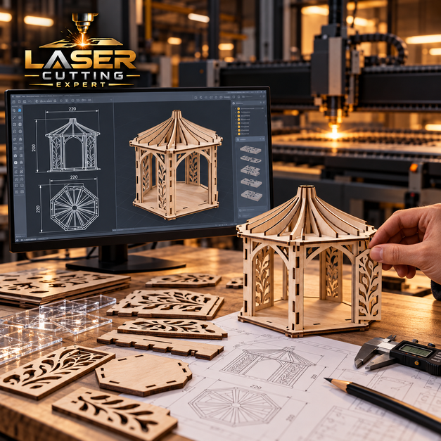
You do not always need a finished manufacturing drawing before speaking to a laser cutting company. Some projects begin with a pencil sketch, an old component, a list of measurements or a basic idea that still needs developing. Laser Cutting Expert provides CAD, design and prototype support from our London workshop, helping customers turn early concepts into practical laser-cut components. Our work includes cad/cam laser cutting, sketch laser cutting, dxf laser cutting and prototyping laser cutting services for businesses, engineers, designers, students, artists and private customers. There is no minimum order, so you can develop one test component before deciding whether the design is ready for repeat production.
CALL OR EMAIL US FOR PRICES
“Order any time of the day or night and receive your order on the same day in London. You are welcome to visit our laser cutting shop for an instant laser cutting service. On-site collection or free delivery can be arranged. Email us at laser@makergroup.uk for a quick quote or call us on 02036339857 for an instant price”.
Same Day Laser Cutting & Delivery
We can arrange a same day courier delivery with customer live tracking. Or customers can collect from our Laser Cutting Expert shop.
OPEN 24 HOUR
We are open 7 days a week, and you can order at any time. There is no last ordering time and no deadline. We also offer an overnight laser cutting service.
100% Satisfaction
High Quality Laser Cutting & 100% Customer Satisfaction Guarantee. Top-Rated Laser Cutting Company on Google.

Free File Check
We offer a free file check and proof before sending your artwork for laser cutting.
Start with What You Already Have
A customer may arrive with a complete engineering drawing, but that is only one possible starting point. We can also discuss sketches, dimensions, photographs, existing parts and basic vector artwork where there is enough information to develop usable production geometry. The first job is understanding what the component actually needs to do. Is it a bracket that must fit existing holes? A sign that needs mounting points? A box that needs to fold together? A decorative screen that must remain strong? Once the function is clear, the design can be prepared around real manufacturing requirements instead of simply tracing a shape without understanding how it will be used.
From Idea to Cut Component
Turning an idea into a physical product usually involves several decisions. Material, thickness, overall dimensions, hole positions, joints and later fabrication all need consideration. Our prototyping laser cutting services help customers work through these questions by creating a physical version that can be tested. The first prototype does not always need to be the final material or finish. Sometimes the important question is whether the geometry works. Once dimensions and fit are confirmed, the design can move into the intended production material. This staged approach is useful for product development because it separates basic design problems from issues related to final manufacturing and finishing.
Sketch Laser Cutting
Sketch laser cutting describes the route from an early hand-drawn concept towards a laser-cut component. A sketch can show overall shape, dimensions, hole locations and the relationship between features, but it still needs to be translated into proper digital geometry before production. The clearer the sketch, the easier this process becomes. Include dimensions, material if known and notes explaining any important features. A photograph of where the part will fit can also provide useful context. We do not simply feed a photograph of a sketch into a machine. The information needs to be interpreted and converted into a controlled production file before laser cutting begins.
What to Put on Your Sketch
A useful sketch laser cutting enquiry should contain enough information to establish scale. At minimum, provide the overall width and height plus dimensions for important holes, slots and cut-outs. If the component has symmetry, indicate the centre line. If holes need to match existing bolts, give their centre-to-centre positions rather than estimating visually. Material thickness is also important, particularly for interlocking parts or components that will be bent. Notes can identify which dimensions are critical and which are flexible. The sketch does not need to look like a professional engineering drawing, but the measurements need to describe the component clearly enough for accurate CAD preparation.
Turning a Sketch into CAD
Once the required dimensions are understood, the sketch can be rebuilt as clean CAD geometry. Lines, arcs, holes and profiles are created at actual manufacturing size rather than traced approximately from the visual drawing. This is where cad/cam laser cutting begins to become useful. The digital model allows dimensions to be checked, repeated features to be positioned consistently and unnecessary geometry to be removed. If the component will later be bent or assembled, those requirements can also influence the drawing. Customers can review the prepared design before material is cut. This reduces the chance of discovering a basic misunderstanding only after the physical part has already been manufactured.
CAD/CAM Laser Cutting
Cad/cam laser cutting connects computer-aided design with the manufacturing process used to create the physical profile. CAD describes the component geometry, while CAM helps translate suitable production information into machine instructions. The advantage is that design changes can happen digitally. A hole can move, a slot can widen or an outside profile can be revised without creating new physical tooling. This makes CAD/CAM useful for prototypes, custom products and repeat manufacturing. Digital control does not remove the need for manufacturing knowledge. The drawing still needs practical feature sizes, suitable materials and realistic tolerances before it becomes a good laser-cutting file.
Why CAD Quality Matters
A laser follows the production geometry it is given. If the CAD contains duplicate lines, accidental gaps or overlapping profiles, those problems can reach the manufacturing stage. Good cad/cam laser cutting therefore begins with clean geometry. Outside profiles should normally form clear closed paths, and intended holes should be distinguishable from construction lines or reference information. Decorative artwork can contain thousands of unnecessary points that make production files harder to manage. Engineering components may instead suffer from duplicated geometry imported from another system. File preparation removes these issues before the job reaches the machine, giving the laser clear instructions about which paths actually need to be cut.
DXF Laser Cutting
DXF is widely used for exchanging two-dimensional CAD geometry. Dxf laser cutting is particularly useful for flat components such as brackets, panels, signs, shims, washers, screens and fabrication blanks. A good DXF can contain the exact profile required at full manufacturing scale. However, the file format itself does not guarantee that the drawing is production ready. Imported DXFs can contain duplicate paths, disconnected lines, incorrect units or unwanted construction geometry. We therefore review the actual content rather than assuming any file ending in .dxf can go directly to the machine. Material, thickness and quantity also need to accompany the drawing.
Preparing a DXF for Production
A production-ready dxf laser cutting file should contain clear geometry at the correct size. Duplicate lines should be removed because the laser should not be instructed to cut the same path repeatedly. Profiles need to be closed where appropriate, and tiny accidental fragments should be deleted. Units should also be confirmed because a drawing created in inches but interpreted as millimetres can obviously create a completely wrong component. If several parts appear in one file, they should be identifiable. Customers do not need to become CAD technicians to order laser cutting, but supplying clean files can significantly reduce preparation time and make urgent production easier.
DXF Files for Engineering Components
Brackets, mounting plates, guards, shims and equipment panels are common dxf laser cutting jobs. The DXF can define outside geometry, holes, slots and cut-outs while an accompanying drawing provides material and critical dimensions. For engineering work, it is useful to distinguish between the geometry file and the technical specification. A DXF alone may not explain tolerance, material grade or what a particular hole is intended to do. If a feature needs secondary machining, that should also be stated. Providing this information prevents the production team from treating every line as though its only requirement is to match the nominal CAD dimension.
DXF Files for Signs and Artwork
Signs, logos, lettering and decorative patterns can also be supplied for dxf laser cutting. Vector artwork is often converted into DXF geometry, but designs created for screens or printing may need modification before physical cutting. Very thin lettering, isolated areas and tiny decorative details can become fragile. Text may also need converting into suitable outlines. For signs, mounting holes and overall dimensions should be confirmed separately from the logo artwork. Materials such as acrylic, stainless steel, aluminium, Corten, wood and plywood each behave differently, so the same visual design may need slightly different production treatment depending on the selected substrate and finished size.
When a 2D DXF Is Enough
Many components do not need a complete 3D model. A flat bracket, sign, washer or panel can often be described perfectly through dxf laser cutting plus material and thickness information. Keeping the file simple can make design changes and production straightforward. Even components that later become three-dimensional may begin as a flat DXF if they are produced by cutting followed by bending. In these cases, the file needs to represent the correct flat development. The final shape may be 3D, but the laser still cuts a two-dimensional blank. Choosing the simplest file type that fully describes the manufacturing operation avoids unnecessary design work.
When We Need a 3D Model
A 3D model becomes more useful when the component has bends, several interacting faces, tubular geometry or complicated assembly relationships. It can help us understand how flat laser-cut parts become the finished object. Enclosures, furniture, frames, product housings and specialist brackets can benefit from this additional context. A 3D model is particularly useful when several components must align. Individual flat files can still be generated for production, but the assembly model helps verify how they relate. For multi-axis work or cutting after forming, 3D geometry may become essential because a simple DXF cannot fully describe where features exist in three-dimensional space.
Prototyping Laser Cutting Services
Our prototyping laser cutting services allow customers to turn digital concepts into physical test pieces before committing to larger quantities. A prototype can answer practical questions that are difficult to resolve on screen. Does the bracket fit? Can the tab enter the slot? Is the sign lettering strong enough? Does the enclosure clear the internal equipment? One component can be produced, tested and revised before another version is made. This works for engineering parts, furniture, signs, packaging, models and consumer products. Because we have no minimum quantity, prototype development does not require ordering dozens of pieces simply to find out whether the first design actually works.
Prototype for Fit
Fit is one of the most useful things to test physically. CAD may show two components touching perfectly, but real material has thickness variation, cutting kerf and manufacturing tolerances. Prototyping laser cutting services can produce test joints, brackets and mating parts so these relationships can be checked before production. This is especially valuable for tabs and slots, furniture connections, enclosure panels and components designed around existing machinery. If a fit is too tight or loose, the CAD can be adjusted using the result from the actual material. One small test coupon can sometimes provide enough information to improve an entire family of related components.
Prototype for Assembly
A product can contain individually correct components that are awkward to assemble together. Physical prototypes reveal whether tools can reach fasteners, whether tabs interfere with welds and whether parts need to be assembled in a particular order. Our prototyping laser cutting services can support complete test kits containing several different profiles. Products may include equipment frames, boxes, display units, furniture and machinery. Parts can be numbered in the design where this helps assembly. Once the prototype has been built, feedback from the fabricator or assembler can be used to improve the CAD. Designing around real assembly can save more production time than optimising each individual part in isolation.
Prototype for Strength and Handling
A decorative panel may look good digitally but become too flexible after hundreds of cut-outs are removed. A small acrylic detail may snap during normal handling. A bracket may need more material around a fixing hole. Prototyping laser cutting services allow these physical behaviours to be checked before the design becomes a repeat product. Laser Cutting Expert manufactures the geometry, but structural or safety-critical performance must be validated by the responsible designer or engineer. For ordinary product development, simply holding and using the prototype can reveal practical issues. Material thickness or pattern density can then be changed before further production.
Prototype for Appearance
Not every prototype is about mechanical fit. Signs, gifts, awards, wedding products and decorative panels often need visual testing. Sketch laser cutting can begin with a rough concept, move into CAD and finish as a physical sample that shows scale, material and detail. A 200 mm sign can feel very different from the same design displayed on a computer monitor. Wood may show darker edges, acrylic may interact with light and Corten steel will change appearance as it weathers. A physical sample allows the customer to approve these characteristics before a full set or larger final product is manufactured.
Bracket Design and Prototyping
A custom bracket is a good example of how CAD and prototyping work together. The customer may begin with dimensions and mounting-hole positions rather than a formal drawing. We can prepare suitable geometry, manufacture one test piece and allow the customer to check it against the actual equipment. If a bend is required, the flat development needs to account for material thickness and bend radius. Slots may be added for adjustment, while unnecessary material can sometimes be removed to reduce weight. Load-bearing brackets require engineering validation. Our role is to help convert the approved design information into a manufacturable laser-cut component.
Enclosure Design Development
Enclosures contain many interacting features: outside dimensions, bends, lids, ventilation, cable entries, displays, switches and mounting points. Cad/cam laser cutting allows these features to be coordinated before the first blank is manufactured. A prototype can then be folded and fitted around the actual equipment. This often reveals details that are difficult to predict digitally, such as cable clearance or tool access. Once confirmed, the flat pattern can become the basis for repeat production. Electrical safety, ingress protection, EMC and regulatory requirements remain with the equipment manufacturer. The prototype confirms geometry and assembly rather than automatically establishing compliance of the completed electrical product.
Furniture Prototype Development
Furniture can combine laser-cut plates, brackets, screens and decorative inserts with wood, glass, upholstery or tubular frames. Prototyping laser cutting services allow designers to check these interfaces physically. A table plate can be tested against the timber top, a bracket can be checked inside a frame and a decorative panel can be reviewed at full scale. CAD can then be adjusted before the product enters a repeat range. Furniture that supports people or heavy loads requires appropriate structural design and testing. Laser-cut prototypes are useful for developing the geometry, but the furniture manufacturer remains responsible for ensuring the finished product performs safely in normal use.
Sign Design from Basic Artwork
Customers do not always have a manufacturing-ready sign file. They may provide a logo, PDF, image or simple drawing. Suitable artwork can be rebuilt into vector geometry for dxf laser cutting, with attention to letter strength, mounting and physical size. A printed logo can contain shapes that are impossible as individual cut pieces because some areas have no connection. These details may need bridges, backing panels or a different construction method. Materials can include acrylic, stainless steel, aluminium, brass, Corten, wood and plywood. A prototype or scaled sample can help confirm whether small details remain readable once the design becomes a physical sign.
Decorative Panel Design
Garden screens, privacy panels, wall panels and furniture inserts often begin as artwork rather than engineering drawings. CAD preparation converts that artwork into cuttable geometry while maintaining enough material for the panel to remain stable. Sketch laser cutting can be particularly useful when the customer begins with a hand-drawn botanical or geometric idea. Repeating elements can then be organised digitally. Pattern density, border width and fixing positions all need consideration. Large outdoor panels may also require structural support. A small sample section can be produced first to show the pattern, edge appearance and amount of open area before the complete panel is manufactured.
Architectural Model Design
Architectural models contain small walls, windows, roof sections and façade details that need to fit together at a defined scale. Dxf laser cutting can produce flat model components from card, plywood, MDF and acrylic. CAD makes it possible to derive repeated windows, floor plates and wall profiles accurately. However, true architectural dimensions may become too small at model scale, so some details need simplification or exaggeration. Engraving can represent features that would be too fragile as complete cut-outs. A test section can establish joint fit and material appearance before the full model kit is produced, particularly where many components depend on the same slot dimensions.
Product Design for Interlocking Parts
Tabs and slots are useful for boxes, models, displays, furniture and assembly fixtures. Cad/cam laser cutting can position these features accurately, but the CAD should account for actual material thickness and kerf. A 3 mm plywood sheet, for example, may not measure exactly 3.00 mm. Designing the slot blindly at nominal thickness can produce a poor fit. Prototype joint samples are therefore useful before a full product is nested onto material. Different fit requirements can also be designed intentionally. A temporary display may need easy assembly, while a model kit might need a closer friction fit. The desired behaviour should guide the geometry.
Boxes and Packaging Prototypes
Laser cutting is useful for developing rigid boxes, packaging structures and presentation products before committing to larger manufacturing methods. Prototyping laser cutting services can produce plywood, MDF, acrylic, card and other suitable prototype constructions. CAD can test tabs, hinges, slots, dividers and internal inserts. For folded card products, crease and fold strategy also needs consideration because cutting alone does not automatically create a practical carton. Foam inserts can be developed alongside the outer box where products need organised presentation. A prototype allows the customer to place the actual item inside and identify clearance problems before ordering a complete production quantity.
Machine Panel Prototypes
Control panels and machine faces often contain holes for switches, displays, emergency stops, connectors and ventilation. Dxf laser cutting can position these openings according to the equipment layout. Before repeat production, one prototype panel can be fitted to the actual machine. This confirms whether component manufacturers’ nominal dimensions match the physical hardware and whether operators have enough space around controls. If the panel will be bent, the flat development should be checked after forming. Machine safety and electrical compliance remain the manufacturer’s responsibility. Prototyping simply gives the design team a physical opportunity to verify the geometry before more panels are manufactured.
Jigs and Templates
Design support can also create workshop aids rather than finished customer products. Templates, drilling guides, positioning plates and assembly jigs can be prepared through cad/cam laser cutting where suitable. These tools can help repeat manual operations more consistently. Acrylic, plywood, steel, aluminium and other materials may be used depending on the application. A template intended only for marking does not need the same material as a welding fixture. Heat, wear and load should therefore influence material choice. If a jig controls a safety-critical manufacturing operation, the responsible engineer should establish its design and validation requirements rather than treating it as an ordinary decorative laser-cut part.
Reverse Engineering Simple Flat Parts
An existing flat component can sometimes provide the information needed to create a replacement drawing. Dimensions, hole locations and profile geometry can be measured and rebuilt into CAD for suitable dxf laser cutting. This can help with discontinued brackets, machine covers, spacers and simple replacement parts. Reverse engineering should not be confused with copying unknown safety-critical components without design information. Material grade, heat treatment and original engineering intent may not be visible from shape alone. For ordinary non-critical parts, a test component can be manufactured and checked against the assembly before the CAD is treated as an approved repeat production file.
Working from Photographs
Photographs are useful for explaining a project but usually do not provide enough information on their own for accurate manufacturing. Perspective distortion makes reliable dimensions difficult to obtain. For sketch laser cutting, a photograph can be combined with measurements and a simple drawing to show where features belong. If you are replacing a component, placing a ruler in the photograph can provide context, but critical dimensions should still be supplied separately. Photographs are particularly useful for showing how a bracket fits, where a sign will be installed or what an assembly looks like. They support CAD preparation rather than replacing dimensional information.
Material Choice During Prototyping
The final production material is not always necessary for the earliest prototype. A designer may first need to confirm shape, size and assembly. Suitable lower-cost material can sometimes answer those questions before the final metal or specialist sheet is used. Later prototypes can then move closer to production specification. Our prototyping laser cutting services can support this staged development where technically appropriate. Material substitutions should not be used for structural or performance testing because different materials behave differently. A plywood mock-up can prove geometry but cannot establish the strength of a steel component. The purpose of each prototype should therefore be clear before its material is chosen.
Choosing Material Thickness
Thickness affects more than strength. It changes weight, flexibility, bend behaviour, slot fit and the practical size of laser-cut features. During cad/cam laser cutting design, thickness should therefore be treated as part of the geometry rather than an afterthought. Interlocking products depend directly on it, while brackets may need sufficient thickness to resist bending. Decorative panels can become unnecessarily heavy if over-specified. For engineering parts, the responsible designer should establish thickness according to loads and application. We can help explain manufacturing implications, but we do not replace structural engineering where safety or load capacity needs to be calculated and validated.
Designing Holes Properly
Holes may provide fastener clearance, adjustment, alignment or access. Each purpose can require different geometry. During dxf laser cutting preparation, customers should distinguish ordinary clearance holes from precision locating features. Very small holes relative to material thickness may not be ideal for direct laser production. Bearing, dowel or precision pin holes can require secondary drilling or reaming. Slots can provide adjustment but need enough material around them to avoid weakening the component. Where a prototype needs to fit existing hardware, the physical bolts, switches or connectors should be checked rather than relying solely on assumed dimensions from an old drawing.
Designing for Bending
A bent component begins with a flat development. The CAD needs to account for material thickness, bend radius and the forming method so the finished part reaches the required dimensions. Cad/cam laser cutting can produce the flat blank, but an incorrect bend allowance will still create an incorrect final component. Holes positioned too close to bends can distort. Corner reliefs may also be needed on trays and enclosures. Prototype bending is valuable for new parts because the physical result can be measured and the flat development adjusted. Once the geometry is confirmed, the approved file can support repeat cutting and forming.
Designing for Welding
Laser-cut parts can be designed to make fabrication easier. Tabs, slots, notches and locating edges can help pieces sit in the intended position before welding. Prototyping laser cutting services allow these joints to be tested physically before a larger fabrication kit is released. The fit should not be so tight that there is no allowance for real material and cutting variation. Weld access also matters. A clever CAD joint is not useful if the welder cannot reach the seam. Structural welding needs approved engineering and fabrication procedures. CAD can support accurate assembly, but it does not determine whether the completed welded structure is safe.
Designing for Engraving and Identification
Parts can include names, numbers, assembly references or decorative information alongside the cut geometry. Where suitable, our related CNC Laser Cutting service can work from controlled digital profiles while identification requirements are planned into the wider manufacturing file. Small information may be better engraved than cut through completely. This can be useful for assembly kits where individual components look similar. Engineering drawings should distinguish permanent product information from temporary workshop identification. If labels contain regulated warnings or ratings, the responsible manufacturer must specify the correct content. CAD controls placement and appearance, while compliance depends on the requirements of the finished product.
Designing for Finishing
Painting, powder coating, anodising and polishing can influence how a component should be designed. Hanging holes may be useful during coating, visible surfaces may need protection and mating areas may require clearance for finish build-up. Cad/cam laser cutting should therefore consider the intended finishing route where it affects geometry. Stainless grain direction can matter on visible panels, while anodised aluminium may require careful surface handling. Components that will be welded should generally complete that fabrication stage before decorative finishing. Planning the full sequence during design reduces the chance of producing a beautifully finished component that then needs drilling, trimming or welding afterwards.
Nesting Prototype Components
A prototype assembly may contain many small parts. Rather than ordering each one as a separate job, compatible profiles can often be arranged together on the same sheet. Dxf laser cutting files can contain several clearly identified components where material and thickness match. This is useful for model kits, furniture prototypes, enclosures and fabricated assemblies. Efficient nesting can reduce waste, but part orientation may still matter for brushed metal, wood grain or later bending. We therefore do not rotate every component purely to maximise sheet usage. Manufacturing requirements come first, followed by sensible material utilisation within those constraints.
Revision One Is Not Always the Final Design
Prototype development naturally involves change. The first physical component may reveal that a slot needs another millimetre, a bracket needs more clearance or lettering needs to be thicker. Our prototyping laser cutting services allow the CAD to evolve after real testing. Drawing revisions should be clearly controlled so an old file does not accidentally return to production later. Once a design has been approved, it can be assigned a stable part or revision reference. This becomes increasingly important when several similar versions exist. Good revision control is one of the differences between casual prototype experimentation and a design that is ready to become a repeat manufactured product.
Moving from Prototype to Production
A successful prototype becomes the reference for future manufacturing. Before scaling up, dimensions, material, thickness and any finishing requirements should be confirmed. The approved dxf laser cutting or CAD file can then support short batches or larger repeat quantities. It is worth resisting the temptation to keep making small unrecorded changes once production begins. If a component needs modification, create a new controlled revision. This helps ensure replacement parts manufactured months later still match the intended version. Product development is therefore not complete merely when the first prototype works; it also requires converting that successful geometry into reliable production information.
Small Batch After Prototype Approval
Not every successful product needs immediate mass production. A customer may approve one prototype and then order ten or twenty pieces for a trial launch. Prototyping laser cutting services can therefore lead naturally into small-batch manufacturing. This works for specialist equipment, furniture, signs, products and replacement components where demand is still developing. A small batch also provides more information about assembly time and real manufacturing consistency. If another improvement is discovered, the CAD can be revised before larger quantities are produced. Laser cutting suits this gradual scaling because digital geometry can be reused without requiring dedicated cutting dies for each version.
Design Support for Students
Students working on architecture, engineering, product design, art and model-making projects can use sketch laser cutting and CAD support when their ideas are not yet ready for manufacturing. A basic drawing can be developed into suitable cut geometry for models, prototypes, displays and project components. Material choice should reflect what the prototype is intended to demonstrate. Card and plywood may be useful for early models, while acrylic and metal can support later presentation or functional development. University deadlines can be tight, so supplying dimensions and files early is helpful. Suitable urgent work can be considered through our 24/7 London production service.
Design Support for Artists and Makers
Artists and makers may begin with hand drawings, illustrations or patterns rather than engineering CAD. Sketch laser cutting can translate suitable artwork into cuttable geometry for wall art, jewellery, stencils, decorative screens, ornaments and layered designs. The artwork may need simplification so narrow bridges and isolated shapes survive physically. Material choice also changes the appearance considerably. Wood produces a different result from acrylic, metal or paper. A small sample can establish scale and edge appearance before a larger artwork is produced. The objective is to preserve the character of the original design while adapting it enough to work as a real manufactured object.
Design Support for Businesses
Businesses may need CAD assistance for a new product, replacement component, display system or internal workshop part. Cad/cam laser cutting allows the project to move from dimensions and concept information into a repeatable manufacturing file. This can be particularly useful for companies that do not maintain an in-house CAD department. We can help with suitable production preparation, while engineering-critical design decisions remain with the responsible manufacturer or engineer. Once approved, the digital files can support later orders. Businesses should retain clear part references so future staff can identify which component and revision needs to be manufactured without relying on informal descriptions.
Customer-Supplied CAD Files
Customers with their own CAD team can send production files directly. Dxf laser cutting is common for flat parts, while more complicated projects may include additional drawings or 3D models. We need the material, thickness, quantity and any important tolerance or finishing information alongside the geometry. Files should represent the latest approved revision. If several versions are supplied without explanation, it can be unclear which one is intended for production. We review suitable files before cutting, but customers remain responsible for approving the component design. A technically clean CAD file can still represent the wrong part if the underlying engineering information is incorrect.
CAD Does Not Replace Engineering
A component can be drawn accurately in CAD and still be unsuitable for its intended application. Structural brackets, machine guards, pressure-related components and safety-critical products require appropriate engineering beyond geometric drawing. Cad/cam laser cutting reproduces approved geometry; it does not calculate safe loads or certify a design automatically. The same applies to medical, automotive and aerospace components where additional quality and regulatory requirements may apply. We can help make a design manufacturable, identify obvious cutting issues and prepare suitable production geometry, but the responsible designer, engineer or manufacturer must validate performance where the component’s failure could create a safety risk.
Same Day CAD and Prototype Cutting London
Laser Cutting Expert operates 24/7 in London, including weekends and bank holidays. Suitable production-ready dxf laser cutting can often move faster than projects requiring extensive drawing development. Where CAD needs to be created from a sketch, turnaround depends on how complete the dimensions and information are. Suitable prototypes can be considered for same-day production when the design, material and machine capacity allow. Same-day courier delivery is available across London for appropriate completed work. Customers with urgent sketch laser cutting requirements should provide all measurements and reference information together, reducing the time lost waiting for missing dimensions before CAD preparation can begin.
CAD, Design and Prototyping Across the UK
Our CAD and prototyping laser cutting services are available to customers throughout the UK. You can send a sketch, DXF, CAD drawing, dimensions or suitable design information electronically without visiting the London workshop. We work with businesses, engineers, fabricators, designers, students, artists and individual customers. Projects can begin with sketch laser cutting, move into cad/cam laser cutting, use dxf laser cutting for the approved profile and then develop from one prototype into repeat production. Suitable completed work can be delivered nationwide, including next-day options where the production schedule and parcel requirements allow. There is no minimum order at any stage of the development process.
FAQs About CAD, Design & Prototyping
1. Can you laser cut from a hand-drawn sketch?
Yes. Sketch laser cutting projects can begin from a clear drawing with dimensions and material information. The sketch is converted into suitable digital geometry before production.
2. What is CAD/CAM laser cutting?
Cad/cam laser cutting uses computer-aided design and manufacturing information to turn digital geometry into machine-controlled laser-cut components.
3. Do you accept DXF files?
Yes. Dxf laser cutting is commonly used for flat brackets, panels, signs, screens, washers, shims and fabrication components.
4. Can you create a DXF for me?
Yes, where sufficient dimensions and design information are available, we can help prepare suitable production geometry.
5. Can you produce only one prototype?
Yes. Our prototyping laser cutting services have no minimum order, so one test component can be produced before a larger batch.
6. Can you work from a photograph?
A photograph can help explain the project, but accurate dimensions are normally still required before manufacturing CAD can be prepared.
7. Can you prototype an enclosure before production?
Yes. A flat enclosure blank can be cut and tested through forming and assembly before the design moves into repeat manufacturing.
8. Can you modify my existing CAD file?
Suitable production changes can be discussed, including geometry clean-up, hole changes and other manufacturability adjustments. Engineering-critical changes still require customer approval.
9. Do you provide urgent prototype laser cutting?
Yes. Suitable projects can be considered for same-day London production, depending on CAD readiness, material availability and complexity.
10. Can I use the same approved CAD for repeat orders?
Yes. Once a design is approved, the controlled production file can support later orders. Any future changes should be managed as a new revision.